 EseeCloud Help Center
OOSSXX HD PoE Security System Manual
Full manual for the OOSSXX HD PoE NVR security system — packing list, NVR and PoE camera specs, port diagrams, app and CMS setup, Cloud ID remote access, recording, motion detection, audio, and FAQ.
This is the OOSSXX HD PoE Security System Manual for a Power over Ethernet (PoE) NVR kit — a PoE NVR with built-in PoE network ports paired with HD PoE IP cameras. Each camera connects to the NVR with a single Ethernet (RJ45) cable that carries both power and video. This manual covers the packing list, NVR and camera specifications, port diagrams, the EseeCloud / IP PRO mobile app, the EseeCloud PC software (CMS), Cloud ID remote access, recording and motion detection, audio, and a full FAQ.
Please scan the QR code on the back cover and register within 7 days to activate your membership and free two-year warranty.

Before You Begin
Thank you for purchasing our products. Be sure to read this instruction manual thoroughly before you use the product appropriately.
- After receiving the product, please double-check product parts. Contact our customer service if it has damaged or missing parts, wrong item, etc.
- We recommend that you do the installation work after confirming that the product is working properly. (Make sure the camera image is properly displayed on the monitor or HD TV.)
- Before installation, please scan the following link or QR code to watch the installation demo video on YouTube.
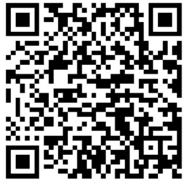
- Cannot get any display on home monitor from the NVR system. There is NO Picture if All-in-One Computer or Laptop is connected to NVR Box directly. Please DON'T do that. The default output resolution of the NVR system may not be compatible with some monitors. If the image does not display properly when connected to monitor, please refer to 14. FAQ 12.
- To make sure the safety of your system, please change the password on your monitor screen. Right click on the home screen of your monitor, navigate to System admin → click User on the left menu bar → Set password → Create a password and type it in the field (keep it short, 8 characters max.) → repeat new password → click OK. Be sure to remember your password.
Safety Notice
- Please do not store or use the NVR in a place that is hot, humid, dusty or oily, or subject to vibration.
- Please place the NVR horizontally and install it in a well-ventilated place. Do not block the ventilation holes.
- Please do not place anything on the NVR. Be careful not to get wet.
- Please note that if the ambient temperature and humidity are high, water vapor may appear inside the product due to the temperature difference.
- Check the supply voltage. Please do not use voltages other than the indicated power supply voltage. Keep power cords away from heating equipment.
- If dust collects inside the device, it may cause malfunction. We recommend that you clean it regularly. Be sure to turn off the power when cleaning this product.
- For your safety, please be sure to turn off the power when moving or not in use for a long time.
- If you find abnormal conditions such as smoke and odor, please stop using it immediately and turn off the power.
1. Product Parameters
POE Security NVR Specification
| Name | OOSSXX POE NVR |
|---|---|
| Video input | 4ch/8ch/16ch — HD 5.0MP/8.0MP |
| HDMI Output | 1ch. Resolution: 1024x768,1280x1024,1366x768,1440x900,1920x1080,4K/30Hz |
| VGA Output | 1ch. Resolution: 1024x768,1280x1024,1366x768,1440x900,1920x1080 |
| Resolution | HD 5.0MP/8.0MP |
| Playback | 1ch/2ch |
| Recording | Manual, time, motion detection, alarm |
| Storage | 1 SATA |
| Storage capacity | MAX 6TB for each HDD |
| Network interface | 1 RJ45 100M |
| USB interface | 2 USB2.0 |
| Power consumption | ≤15W without hard drive |
| Working temperature | −4°F — +140°F |
| Working humidity | 10%–90%RH |
| Dimension (mm) | 258mm×210mm×42mm |
| Power | DC 48V 2A |
POE Camera Specification
| 5.0 Megapixel | 8.0 Megapixel | |
|---|---|---|
| Model | 5.0 Megapixel | 8.0 Megapixel |
| Sensor | 1/3" Progressive Scan Sensor | 1/3" Progressive Scan Sensor |
| Signal System | PAL/NTSC | PAL/NTSC |
| Resolution | 2560 x 1960 16:9 High Definition | 3840 x 2160 16:9 High Definition |
| Minimum illumination | Color: 0.1 Lux; B/W: 0.01 Lux | |
| Shutter | 1/25s to 1/25,000s | |
| Lens | 3.6mm | |
| OSD | Date Time & Title (NVR system can change Title name) | |
| White Balance | Auto | |
| Day & Night | IR cut filter with auto switch | |
| 3D-DNR | Auto | |
| Mirror/Flip | On / Off (NVR system setup) | |
| Signal /noise rate | > 39.1 Db | |
| Interface | RJ45 | |
| Anti-thunder Level | Standard IEC61000-4-5 |
General Specification
| Working Temperature/Humidity | −4°F to +140°F / 30% to 80% RH |
| Storage Temperature/Humidity | −20°F to +180°F / 20% to 90% RH |
| Power Input | DC12V-1A |
| Power consumption | ≤6W |
| Size | 66*180mm |
| Weight | 500g |
| Level of Protection | IP67 |
Depending on the production time, the product information in this manual may differ from the actual product. Note that it matches the real product.
Before setting the camera system, please visit our website www.oossxx.com to watch demo videos. You can also scan the QR code on the product to get our after-sales support.
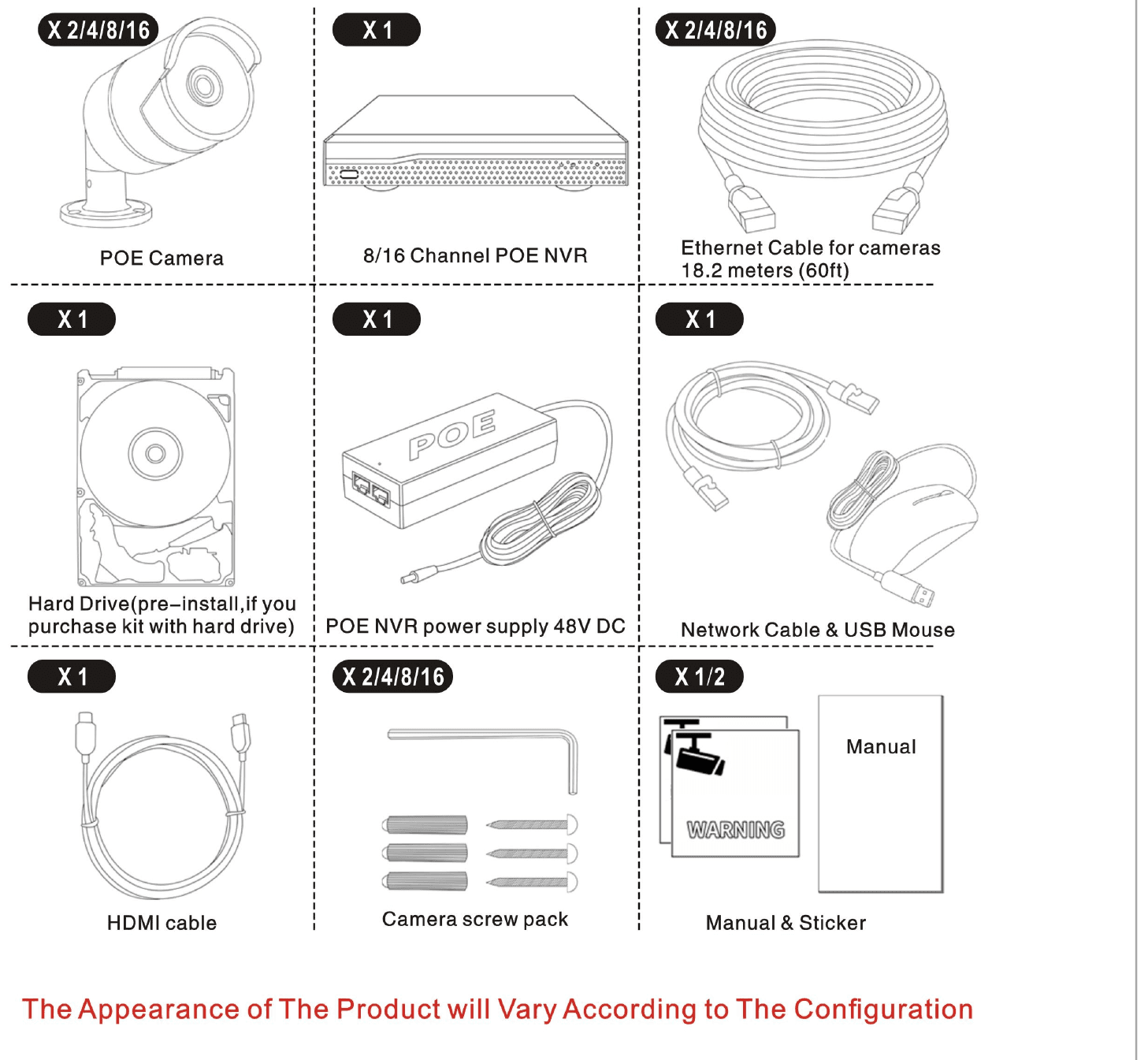
2. System Components
The appearance of the product will vary according to the configuration.
- POE Camera × 2/4/8/16
- POE 8-Channel Network Video/Audio Recorder × 1
- POE NVR power supply 48V DC × 1
- Ethernet cable for cameras 18.2 meters (60ft) × 2/4/8/16
- Network cable 3 feet × 1
- Waterproof connector for network cable × 2/4/8/16
- Camera screw pack × 2/4/8/16
- Hard Drive (pre-install, if you purchase kit with hard drive) × 1
- HDMI cable & USB mouse × 1
- Manual × 1
- Sticker × 4/8
3. Installation Settings
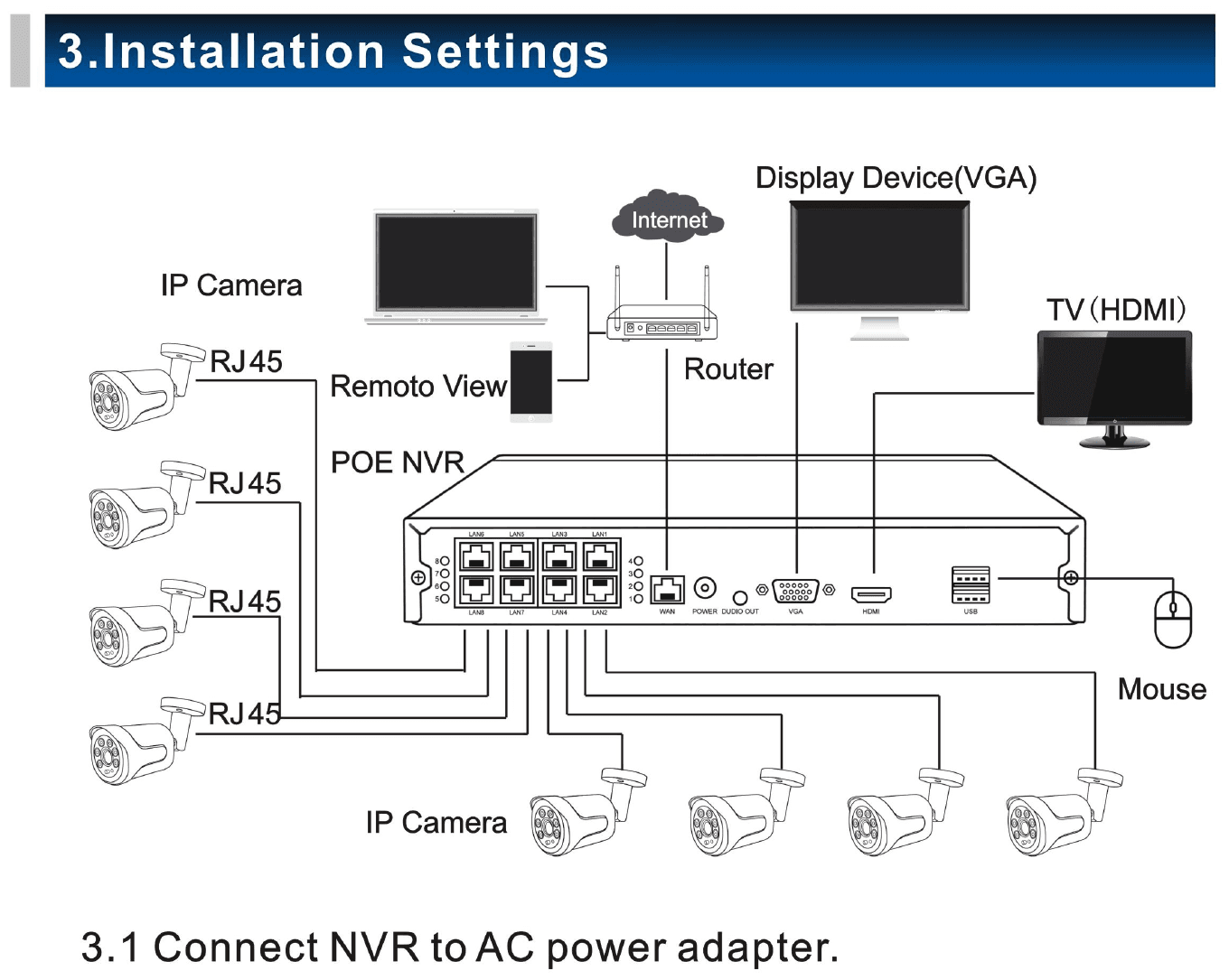
3.1 Connect NVR to AC power adapter
NVR AC power adapter is 48V 2A. Please make sure the power connect is right. Power adapter supports input from AC 110-240V.
3.2 Connect NVR to monitor with HDMI / VGA cable
Please do not use a laptop monitor or all-in-one PC as a camera system monitor. TV or PC monitor would be a perfect choice. Please use an HDMI cable or a VGA cable to connect NVR to monitor. Switch TV to HDMI mode or VGA mode.
3.3 Connect the mouse to the USB port at the back of NVR
POE NVR System — Interface Description
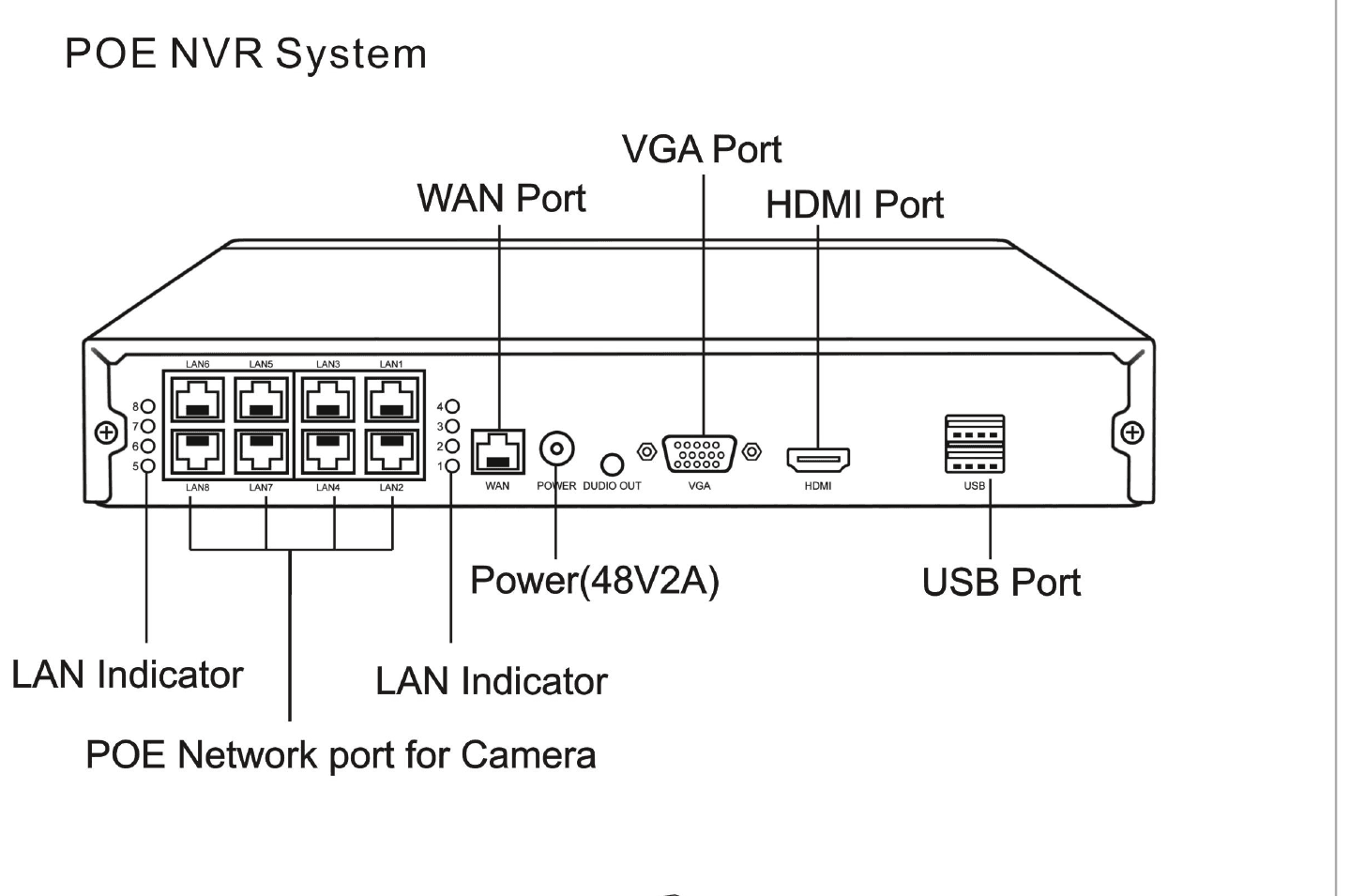
- WAN port: Connects to the Internet.
- VGA port: Hooked up to liquid crystal display.
- HDMI port: Connects to high-definition TV.
- USB port: Connects to mouse or USB device.
- NVR power input: 48V 2A.
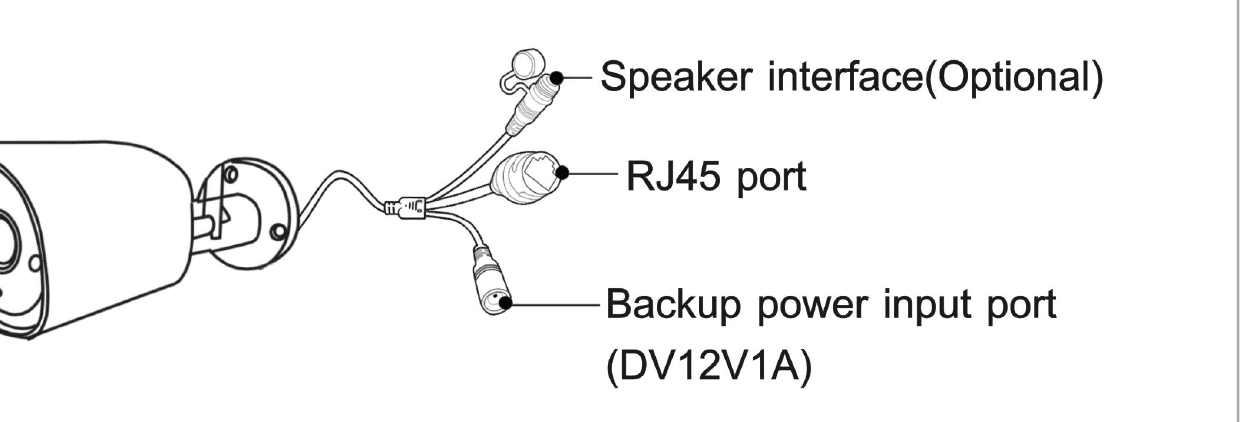
- RJ45 port: For matching code and wired connection between IPC camera and NVR. Our POE NVR kit is already matched code before delivery. If you need to re-match code, please refer to how to add IP cameras (as shown in 3.6).
3.4 Log in your account
No password is required for first time log in, as shown below. There's no password for initial log in, shown as picture below. Please change your password after initial system setup.
- Open the System Setup → System Admin → User → Set Password screen from the main menu.
- Enter password (up to 12 digits).
| Username | admin |
|---|---|
| Password | (blank) |
3.5 Connect the camera to the NVR with LAN cable
Cover the lens part of the camera with your hand and check if the infrared LED light glows red. If it does not glow red, the infrared may not be working properly, please contact customer service for help.
3.6 Pair cameras to the system
Cameras are paired to system as default by manufacturer. If cameras lose signal or you need to add other cameras to system, please follow the instructions below to pair them manually:
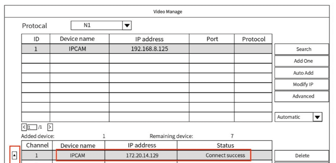
(a) Connect camera to NVR by ethernet cable. (b) Right click on the main interface and select Video Manage (if need password please refer to step 6 mentioned above [Log in your account]). (c) Change Protocol to N1, and click REFRESH. (d) When camera is detected by system, camera information will show up in the upper top table table as picture below and then click Add. (e) After added successfully, camera information will be moved to bottom table, and seen as added device. Please make sure that camera status is CONNECT SUCCESS.
Repeat step 6 if more cameras need to be added.
After cameras are connected successfully, you can mount the camera to the location as planned.
4. APP Settings
Please connect NVR to Router in your property by Ethernet cable. To remote access your camera system, Internet support is required.
4.1 Download
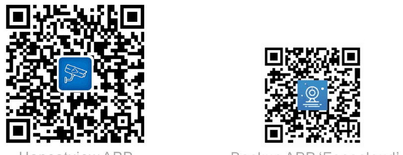
Scan the QR code below to download Honestview App. It can also be downloaded from the app store. Or search Honestview in app store and download accordingly. Or use Backup APP "Eseecloud".
4.2 Register
First an account has to be created by using your email or phone number, then a verification code will be sent to your email or phone number, then you can log in.
Eseecloud is only compatible with system versions above iOS 9.0 and Android 5.1.
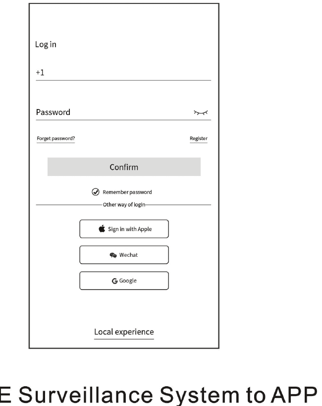
4.3 Connect POE Surveillance System to APP
There are two ways to connect a POE system to APP:
- (a) Scan QR code
- (b) Log in your cloud account
(a) Scan QR code
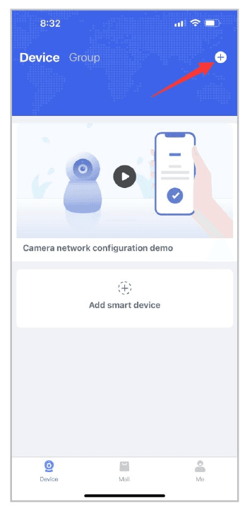
Click the + icon in the upper right corner to enter the scan code interface.
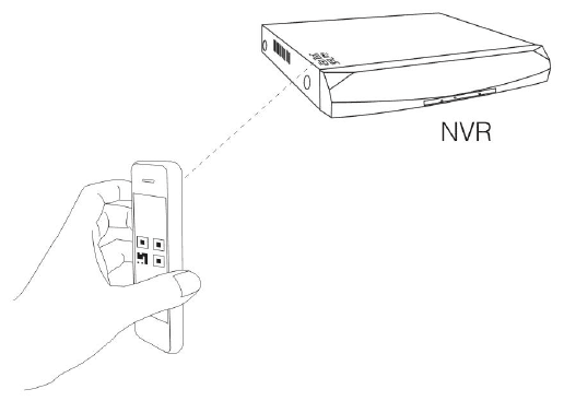
Scan the Cloud ID QR Code on the NVR.
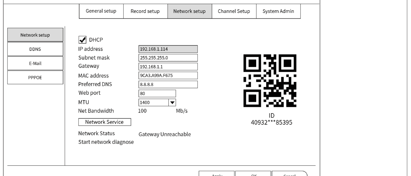
Or scan the QR code at NVR System → System Setup → Network Setup → Network Setup.
(b) Log in your Cloud account
Click the + icon in the upper right corner to enter the scan code interface, then click other ways to add.
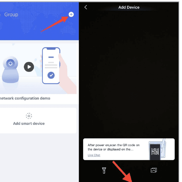
Choose kit, then enter your Cloud ID — you can find your Cloud ID at the NVR cover or system network setup. The Password is the same with your camera system.
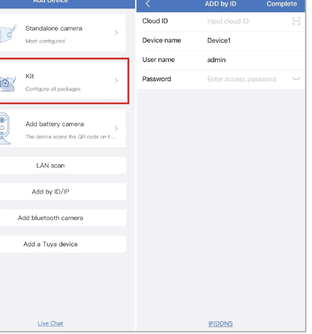
No password required in first time system setup, just enter your Cloud ID, then click complete in the upper right corner, wait for a few seconds until add device successfully.
4.4 APP function description
- 【Cloud Service】: Enter the cloud service.
- 【News】: You can view motion detection notification messages.
- 【Share】: You can grant the camera monitoring permission to others. Up to 3 terminals can be monitored simultaneously.
- 【Play】: recordings saved in HARD DRIVE in NVR box. You can play the saved recording. Hard disk (HDD) is required to use this feature.
- 【Device】: Display all camera systems added to the APP.
- 【Mall】: Enter the mall.
- 【Me】: You can view information, settings, management, etc. Enter cloud services.
- 【SD】: Switch between high definition (HD) and standard definition (SD) modes.
- 【Sound】: You can hear the sound of the monitored location.
- 【Screenshots】: You can save screenshots.
- 【Recording】: You can record surveillance images on your smartphone.
- 【Full Screen】: You can display in full screen.
- 【Zoom】: You can zoom the screen. Only products with PTZ function are supported.
- 【PTZ】: You can control the pan/tilt/zoom functions of the camera. This function is only compatible with products with PTZ function.
- 【Alarm】: Click to make an alarm sound.
- 【Intercom】: Press and hold the call to talk through the camera. This feature is only available for products with call function.
5. Laptop Settings
5.1 Please download CMS EseeCloud
Please visit www.oossxx.com and click Download. For PC (Windows), please download CMS Program for PC (Windows). For MAC, please download CMS Program for Mac.
5.2 Install CMS on your computer / laptop / Mac
5.3 Log in to EseeCloud
Username: admin. Password: keep in blank. Without password, need not input.
5.4 Click ADD to add your camera system on computer
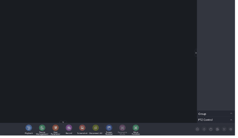
5.5 Fill in CLOUD ID, PASSWORD, NUMBER OF CHANNELS
Cloud ID is at the right down corner of your monitor, please keep Cloud ID online by connect NVR to router with an Ethernet cable.
PASSWORD is your camera system password. Number of Channels means the number of your cameras.
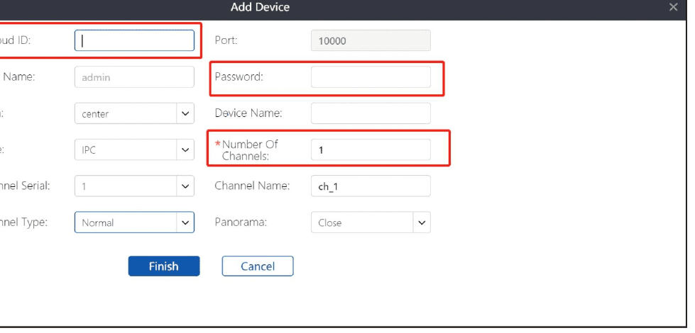
5.6 Click FINISH
Click FINISH and wait for a few minutes to ensure that cameras are added to system successfully.
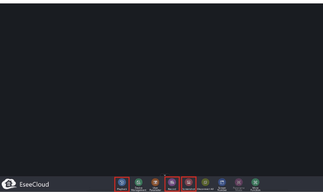
5.7 Playback, Record and Screenshot
You can PLAYBACK, RECORD and SCREENSHOT (hard drive is required to achieve these functions).
6. Email Settings
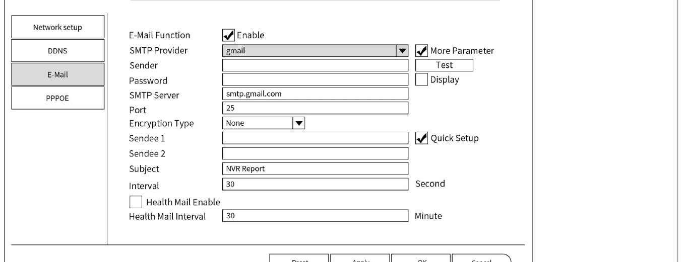
Go to System Setup → Channel Setup → Motion Detection, select the channel as need, check on Email Notice, click Apply to Network Setup → Email.
6.1 E-mail setup fields
In the E-mail setup interface, the following items need to be configured:
- (a) Enable E-mail function.
- (b) SMTP Server: The input format is smtp.live./yahoo./gmail.) com.
- (c) Ports is 25.
- (d) Username: Your username of your mailbox (for example: if your mailbox is [email protected], your username is [email protected]).
- (e) Password: Password of your email. The password must less 10 letters.
- (f) Encryption Type: You don't need to select it, but if the test fails, modify it to SSL.
- (g) Sender: Your email address (for example: [email protected]).
- (h) Sendee: The email address you use to receive email from the sender (for example: [email protected]).
- (i) Subject: default is ok, you can change according to your need.
- (j) Interval: The time interval for receiving emails (if you set a high frequency of alerts and the capacity of the receiving mailbox is small, it may be impossible to receive news due to insufficient capacity.)
- (k) Enable Health Mail Used to detect the NVR's input is running normally.
- (l) Health mail interval: The time interval for sending messages when the device is running normally.
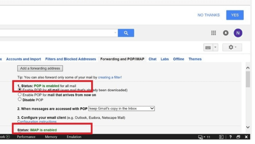
Please enable POP / IMAP in your email account settings.
Mailboxes such as Gmail / Yahoo need to set NVR App Password
Log in your Yahoo account, close two-step verification, meantime Allow apps that use less secure sign in, as below:
7. HDD Settings
7.1 Auto overwrite settings
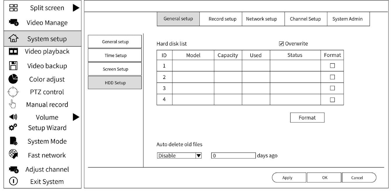
(1) Click System Setup → General Setup → HDD Setup in the main menu. (2) Overwrite ✓ — if the hard drive capacity limit is exceeded, the oldest recorded data will be automatically overwritten. Check it and click Apply.
7.2 Format hard drive
(1) Click System Setup → General Setup → HDD Setup in the main menu. (2) Display hard drive information, select the hard drive to be formatted. (3) Click the Format button.
All data will be deleted after formatting the hard drive.
7.3 Optional Hard drive installation (if original NVR system was purchased without installed HDD)
Please turn off all power before installation.
(1) Unplug your NVR from power, unscrew and remove the top cover. (2) Connect the SATA cable and data cables from the NVR to the corresponding ports on your HDD (as shown). (3) Test if hard drive is functional before put cover back to NVR. If you turn on the power of the NVR without closing the cover, and the hard drive is powered on, you will feel a noticeable vibration in your hand. If you don't feel vibration, try another HDD and try connecting again. (4) Hold the hard drive and NVR gently turn it over and line up the holes on the hard drive with the holes on the NVR. Using a Phillips screwdriver, screw the provided screws into the holes. Assemble the cover.
8. Record Settings
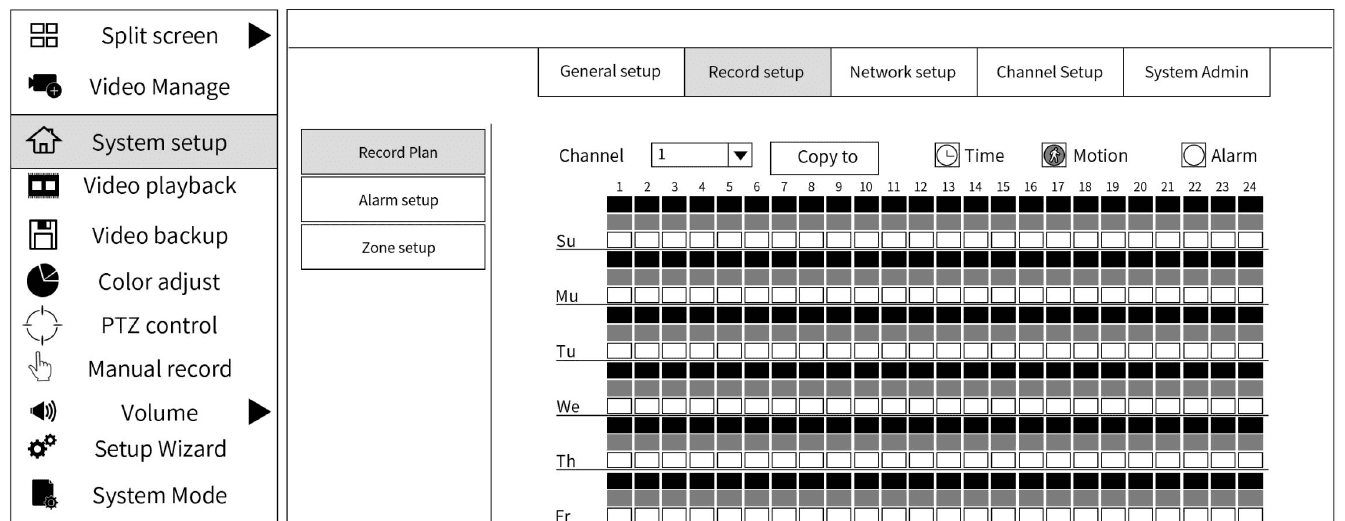
The default setting is continuous recording (24-hour recording) mode. Open System Setup → Record Setup screen of the main menu.
8.1 Set up automatic delete of old files
(1) Click SYSTEM SETUP, GENERAL SYSTEM, HDD SETUP. (2) Click DISABLE, and switch it to CUSTOM, and select days that you want to record (4 cameras and 1 TB hard drive, can record about 30 days).
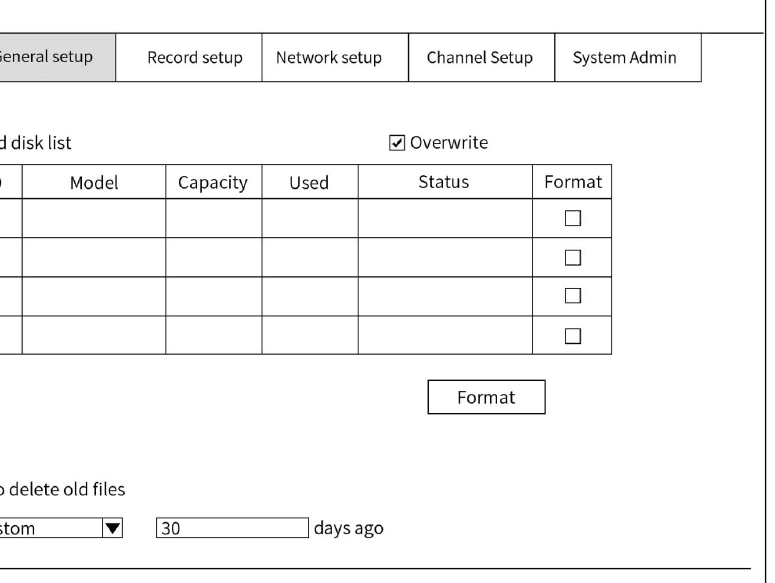
You can choose the automatic coverage mode. The system will automatically delete the old video and keep the new video when the hard disk is full recorded. You can also set your own date to periodically delete old recordings.
8.2 Continuous Recording (24 hours recording)
(1) Select the desired channel for continuous recording. (2) Click the red Time button. (3) Click Select All, and then click Apply. (4) If you want to make the same settings for other channels, click Copy to, select the channel number, click OK, and click Apply.
8.3 Time Recording (time zone specified recording)
(1) Specify time zone. Select the channel to be recorded. (2) Click the red Time button. (3) Hold down the left mouse button and drag to select the date and time zone to be recorded, and click Apply to specify the recording time zone. (4) You can cancel the selected time zone by holding down the left mouse button and dragging the selected time zone and clicking Cancel. (5) If you want to make the same settings for other channels, click Copy to, select the channel number, click OK, and click Apply.
8.4 Motion Detection Recording
(1) Select the desired camera channel for motion detection recording. (2) Click the green Motion button. (3) Hold down the left mouse button and drag to select the date and time zone of the motion detection recording, and click Apply to specify the time zone of the motion detection recording. (4) You can cancel the selected time zone by holding down the left mouse button and dragging the selected time zone and clicking Cancel. (5) If you want to make the same settings for other channels, click Copy to, select the channel number, click OK, and click Apply.
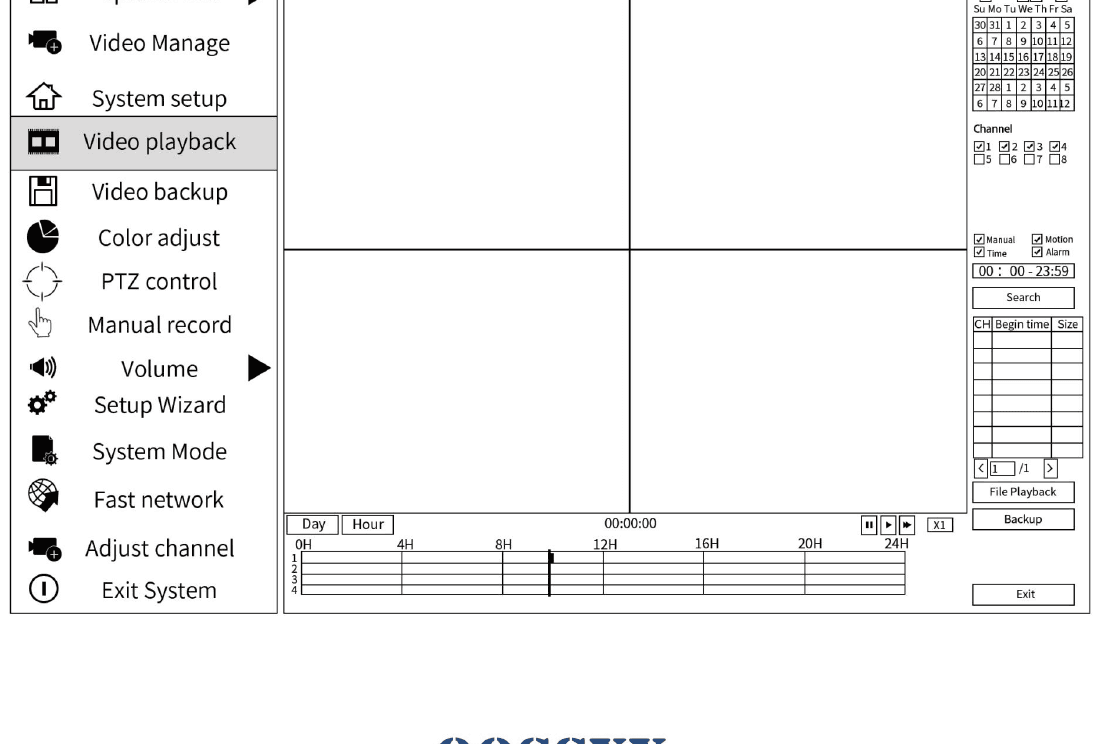
9. Video Playback
Only system with hard drive supports video playback.
- Right click at home video page, click VIDEO PLAYBACK.
- Select the date and time, channels that you would like to play back.
- If necessary, select TIME and MOTION play back.
10. Video Backup
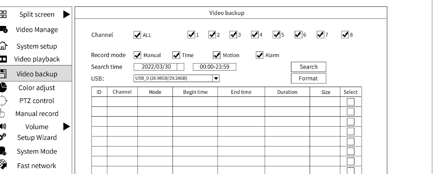
Only system with hard drive supports video backup.
- Right click at home video page, click VIDEO BACKUP.
- Select date, time and channel that the video you would like to back up, and click SEARCH.
- Select the videos that you would like to BACKUP, and click BACKUP button.
- The screen will start count down for one minute, and please quickly unplug the mouse, and insert USB. The system will automatically backup videos in the USB.
11. Motion Detection
11.1 Three ways to receive alarm when motion is detected
- (1) Buzzer: System will make alert, an a triangle alarm sign will show on the left down corner of the screen. Click it, you will see the date, time and channel information when the motion was detected.
- (2) E-mail: A notification will be sent to your email when the motion was detected with a screen shot of the model.
- (3) APP: A notification will be sent to you when the motion was detected.
11.2 Notification Settings
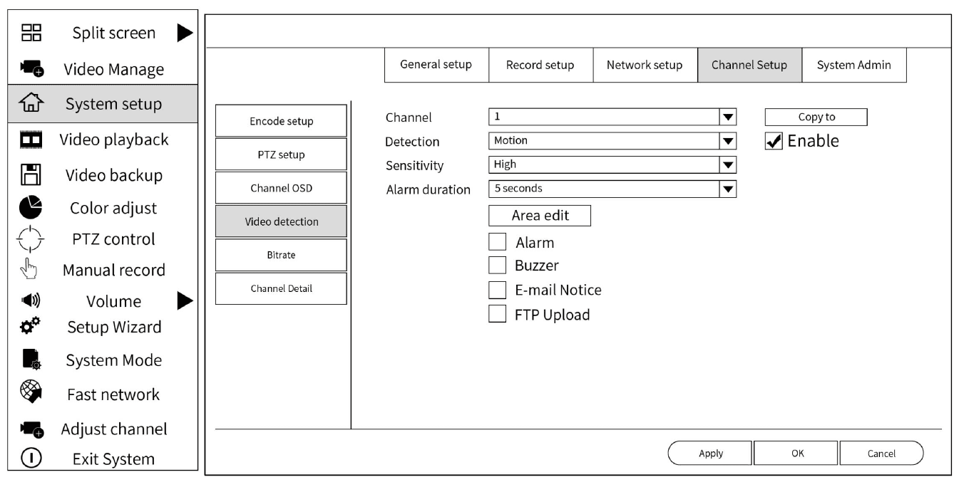
Open the System Setup → Channel Setup → Video Detection interface of the main menu.
(1) Channel: Select the channel that needs email notification, and check Enable. (2) Detection: Select Motion. (3) Check √ before E-Mail Notice. You will be notified by email when movement is detected on the corresponding channel. Check it and click Apply.
Please enable Notification function in your cellphone.
11.3 Function Description
- Buzzer: The NVR has a built-in buzzer, when enabled, the buzzer will sound. When enabled, NVR will beep when motion is detected.
- Email Notice: When enabled, you will receive a notification email when motion is detected.
- APP Alarm: When enabled, the APP will send a notification when motion is detected. (Note: Please turn on the notification function of your smartphone.)
- Full Screen: When enabled, the alarm camera's screen will be enlarged.
11.4 Detection Area Change Settings
By default, full screen is the detection area. Click System Setup → Channel Setup → Video Detection → Edit Area in the main menu to open the detection area editing interface.
(1) Right click Clear All. (2) Hold down the left mouse button and drag to specify the area to be detected. (3) Right-click Return. (4) After completing the settings, click Apply.
12. Audio Function Settings
12.1 Audio Function
(1) Right click with the mouse → Select System Setup. (The login interface appears for the first operation. The default password is blank. Please select OK to log in.) (2) Select Channel Setup → Select a Channel → Configure the Encode Mode as AV Stream → Click Apply.
(1) Do not install the camera in a noisy environment where the sound quality is disturbed for effective recording. (2) Please select the appropriate volume level in order to effectively record sound. (3) Do not install the camera near noisy equipment, such as machines or electrical machinery.
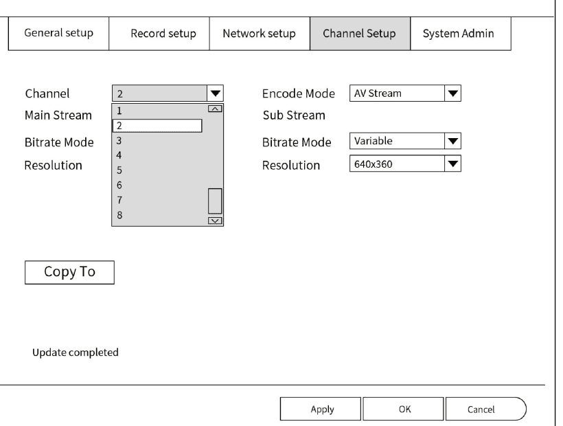
Help — What should I do if I turn on audio function but still no sound?
- Make sure the monitor has a speaker, and the NVR and the monitor need to be connected through an HDMI cable.
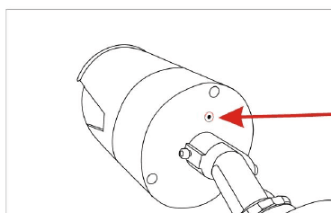
- Please confirm whether the camera has audio function and check if your camera has a microphone hole. (As shown below.)
- The NVR only plays audio from one single camera each time, please make sure that turn on the audio of the selected camera.
12.2 Volume Control
- Please confirm whether the volume of both the monitor and the NVR are appropriate. (As shown below.)
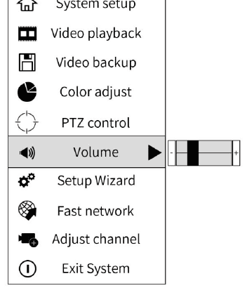
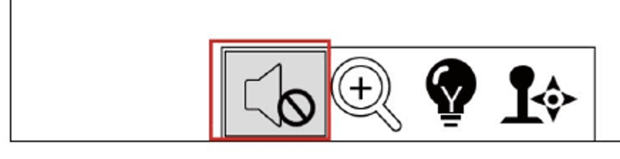
(1) You can select System Setup → General Setup → Volume in the main menu to adjust. (2) Click the Audio marker on the toolbar at the bottom of the main monitoring screen to turn audio on or off.
Toolbar Description
The main-screen toolbar contains the following buttons:
 Audio: Click to turn audio on/off.
- Zoom: Once selected, you can slide the mouse to zoom the screen.
- Floodlight: Click to turn on/off floodlight lighting. (Only for products with floodlight.)
- PTZ: When selected, you can control the PTZ. (Only products with PTZ function can be used.)
13. Other Settings
13.1 Channel Switch
Example: If want exchanging Channel 1 and Channel 3, please click the Video Manage of main menu. Choose Channel 1, click up and down arrows on the left; the Channel list will move Channel 1 exchange to other Channel.
13.2 Screen Flip
(1) Open the Video Manage screen of the main menu, select the channel to be flipped, and click Manual Edit. (2) Click Image Rollover, and then click OK.
13.3 Change Resolution
Main menu → System Setup → General Setup → Screen Setup → VGA Resolution can be changed.
13.4 System Version Information
Go to system setup main menu → System admin version.
13.5 Firmware Upgrade
For system security, if you need to upgrade the firmware, please contact customer service to provide the corresponding firmware.
13.6 Restore Factory Settings
(1) After factory configuration, all NVR system settings and recordings will be reset.
(2) Please backup your important data before clicking Factory setting. (3) After reset, the camera needs to be added (paired) to the NVR system again. (4) Steps: please right click the main interface, select System setup → System Admin → Factory setting, then click Apply → Yes → OK.
13.7 Time Settings
Open the System Setup → General Setup → Time Setup interface of the main menu.
Set Enable for Sync Time √, wait a few minutes to check if the time is in sync. Check it and click OK.
(2) If there is no synchronization or no network environment: Click Advanced to manually set the time.
14. Frequently Asked Questions
1. How long is my warranty? We provide one year warranty for the camera system, including cameras and NVR. It started from the purchase date on your receipt.
2. How do I reset password? Please understand that we are very strict with resetting password for security reason. Please email customer service with your Amazon or Walmart order number, your full name and address. The email address is: [email protected].
3. Can I add more cameras? Yes. Each NVR box can take 8 cameras maximum. You can add more cameras by yourself.
4. Do I have to have a monitor? Yes, for initial setup, you need to have a monitor to see the system. It can be a TV, a computer monitor. It is necessary to have a VGA or HDMI cable to connect it.
5. Why my cellphone doesn't send me motion detection notification? Please make sure that your cellphone doesn't disable notification function.
6. Which time zone I am in? At eastern coast of US, please set your time zone -5:00, and western coast, please set -8:00.
7. Why HDD is not found? Please make sure you have hard drive pre-installed in your NVR. When HDD is not found, please open top of NVR by a screw driver, and unplug and plug them back the wires, which are connected to hard drive. After doing this, please check the middle light at the front of NVR is flashing, and the hard drive is vibrating.
8. Do I need Internet to support the system? To remote access to the system from cellphone and computer, you need Internet to support the system. Please connect the NVR to router in your property with an ethernet cable.
9. The camera working great in day, but in night vision part bright. Pic A:
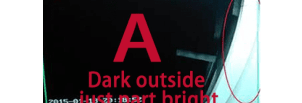
This problem is camera near the wall or others. Camera received reflection from wall. Please adjust the camera installation angle. Avoid the wall. The problem will be solved.
10. The camera working great in day time, but in night vision show reflection. Pic B:
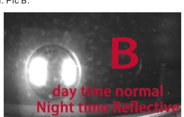
The camera cannot show clear picture of what's outside at night through the window. The windows glasses will reflect to Camera. Please move camera to outdoor, the problem will be solved.
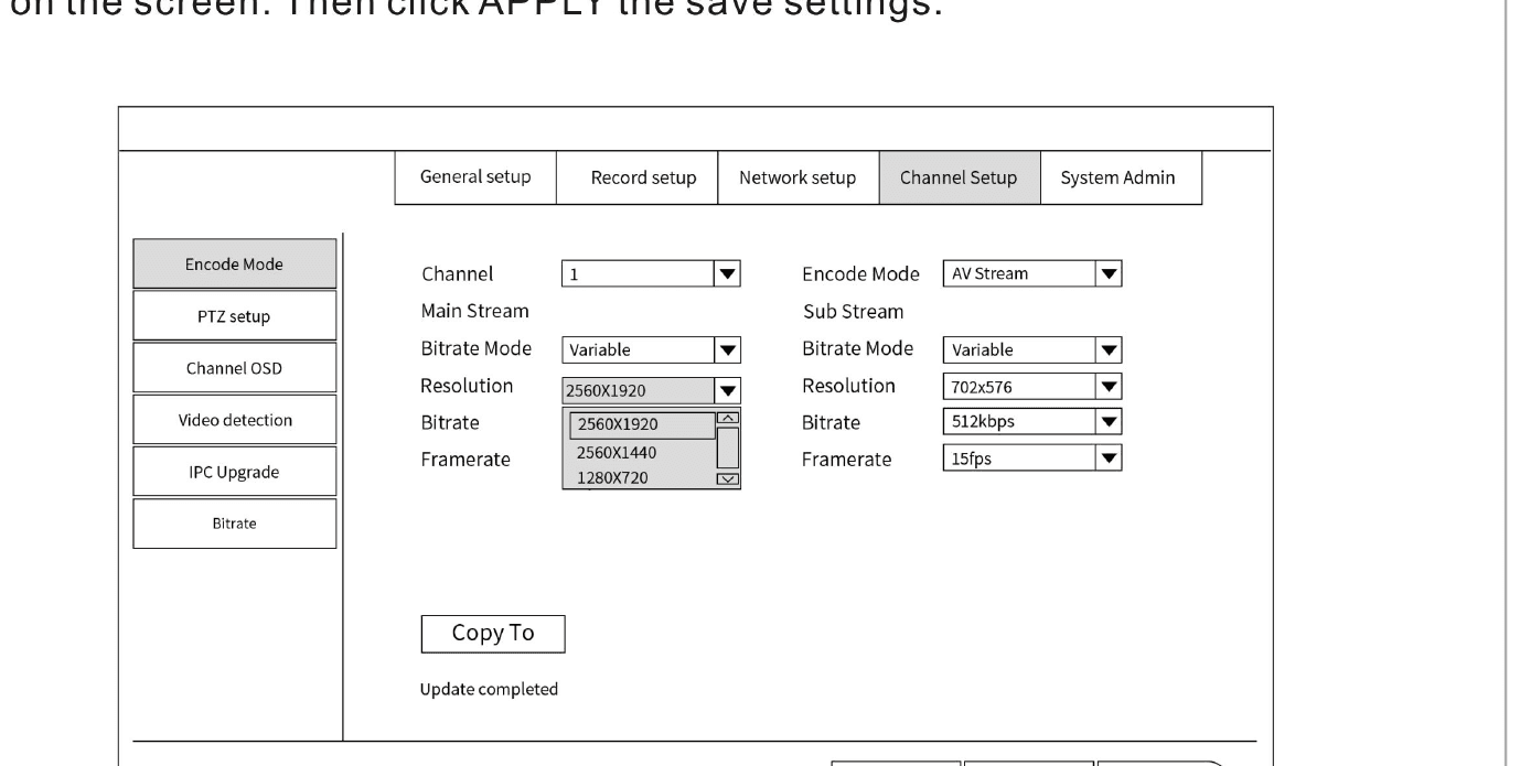
11. What should I do if I get high resolution? When HIGH RESOLUTION show in video management. Go to System Setup → Channel Setup → Encode Mode. Select the channel number and click on Resolution, and choose a lower one than what currently on the screen. Then click Apply the save settings.
12. What should I do if the screen doesn't appear?
If the NVR system screen displays No Signal:
a) Set your HDTV to HDMI mode and connect your NVR to your HDTV with HDMI cable. b) Unplug the NVR and plug it back in again. When you turn on the power, you will find that the NVR is running. c) It will take 2 to 3 minutes for the NVR to fully boot, please wait for a while. Press and hold the left mouse button for about 15 seconds, then release the mouse when you hear a beep. Please check that the image is displayed properly. d) Since the HDMI cable may not display, please try to connect with another HDMI cable. e) Set the HDTV to VGA mode and connect it with a VGA cable to check if it is normal.
If the above screen does not appear, try connecting to another monitor with VGA cable. If the screen is displayed on another monitor, your PC monitor would be a perfect choice.
Please use a HDMI cable or a VGA cable to connect NVR to monitor. Switch TV to HDMI mode or VGA mode.
If you are using an HDMI cable to connect to an HDTV, set the TV to HDMI mode. General setup → Screen setup → change VGA resolution to 1024x768, click OK. Reconnect the NVR to the first monitor and see if the screen appears.
If the above method does not appear, try using an HDMI cable to connect to the HDTV, set the TV to HDMI mode. Then the System setup → System Admin → version.
15. Customer Service
If you have any questions, please contact us before you return the product or if you have any questions. We will try our best to assist you.
| Website | www.oossxx.com |
| [email protected] (reply in 24 hours) | |
| Tel | +1 (352) 900-4656 (Eastern time Monday–Friday 9:00am–5:00pm) |
16. Sponsored — Optional Accessories
The manual closes with advertisements for optional OOSSXX accessories you can order through amazon.com or Walmart.com:
- Junction Box — waterproof, moisture-proof, sun-proof, corrosion-proof and durable. It can be used inside and outside the house and has wide range of uses. Ideal for hiding wires and connectors. Cable entry through rear/bottom. It not only looks good, but also delays the aging of the wires and prolongs the service life of the camera. Choosing a cable box is a wise choice to make the security camera better at protecting your house.
- Solar Power Deck LED Light Clip-On Yard Security Sign Spotlight — automatic solar charging by day, automatic luminous at night, with a "24 HOUR VIDEO SURVEILLANCE PROTECTION" sign.
- Universal Security Camera Sun Rain Cover Shield — protective roof for Dome/Bullet outdoor cameras. Compatible with Nest/Ring/Arlo/Dome/Bullet cameras and most other brands of indoor or outdoor cameras. Made of ABS material, durable, reliable and lightweight. Size 10.63" X 5.51" (27cm X 14cm).
- 3MP HD Hidden Camera Clock Alarm — Mini spy camera, wireless, with remote live view, motion detection alarm, night vision, indoor Wi-Fi nanny cam, two-way audio, real 3MP live stream, clear siren and real-time alert.
Active Two-Year Warranty
Please register your purchase, activate your membership & free two-year warranty. Thanks for purchasing OOSSXX Security Product.
Just send your order ID and e-mail to [email protected]. We will activate your membership & extend free warranty from 1-year to 2-years. The "Activate 2-years warranty receipt" will send to your e-mail in 48 hours. Your purchase will be 100% covered under 2 years warranty. Enjoy.
- What is Amazon order ID? It's a 17-digit code that will be in this format: 123-4567890-1234567.
- What is Walmart order ID? It's a 13-digit code that will be in this format: 1234567890123.
Looking for more help? Visit the Help Center, the ESeeCloud App User Guide, or the ESeeCloud CMS guide.
OOSSXX HD Video Security System Manual
Full manual for the OOSSXX HD-Analog DVR system — packing list, DVR and AHD camera specs, connection diagrams, app and CMS setup, Cloud ID remote access, e-mail alerts, recording, motion detection and FAQ.
OOSSXX Mini Station Wireless Security Camera System Manual
Wireless Security System Manual for the OOSSXX Mini Station kit — packing list, bullet camera and Station interfaces, network diagram, EseeCloud / IP PRO app setup, camera placement, pairing a new camera, and FAQ.