 EseeCloud Help Center
OOSSXX Mini Station Wireless Security Camera System Manual
Wireless Security System Manual for the OOSSXX Mini Station kit — packing list, bullet camera and Station interfaces, network diagram, EseeCloud / IP PRO app setup, camera placement, pairing a new camera, and FAQ.
This is the Wireless Security System Manual (Mini Station) for the OOSSXX kit — a mini base Station paired with Wi-Fi bullet cameras. It covers the packing list, the camera and Station interfaces, the working network diagram, app installation and login, notification, preview and playback, camera placement, how to add a new camera to the Station, and a short FAQ.
1. Setup Demo Video
Scan the QR code below to view the setup demo on YouTube.
2. Packing List
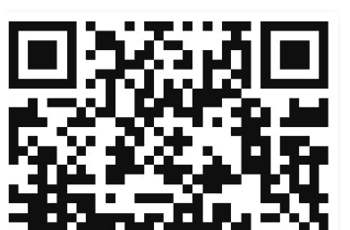
Product sales configuration is different. Please refer to the actual product.
| Item | Quantity |
|---|---|
| Camera | x2 |
| Power supply for Station | x1 |
| Network Cable | x1 |
| Quick Start Guide | x1 |
| Certificate | x1 |
| Screw package | x2 |
| Station | x1 |
| Power supply for Camera | x2 |
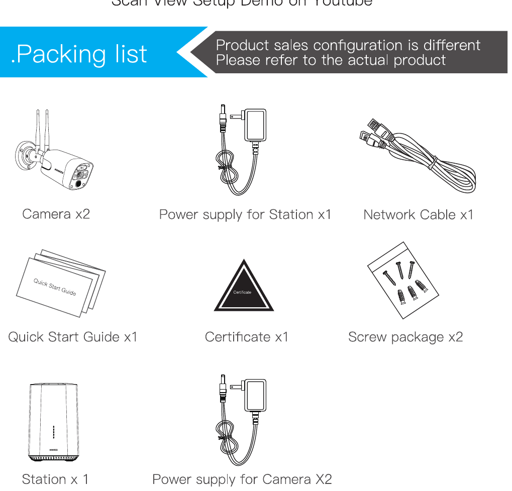
3. Interface Description
3.1 Bullet Camera
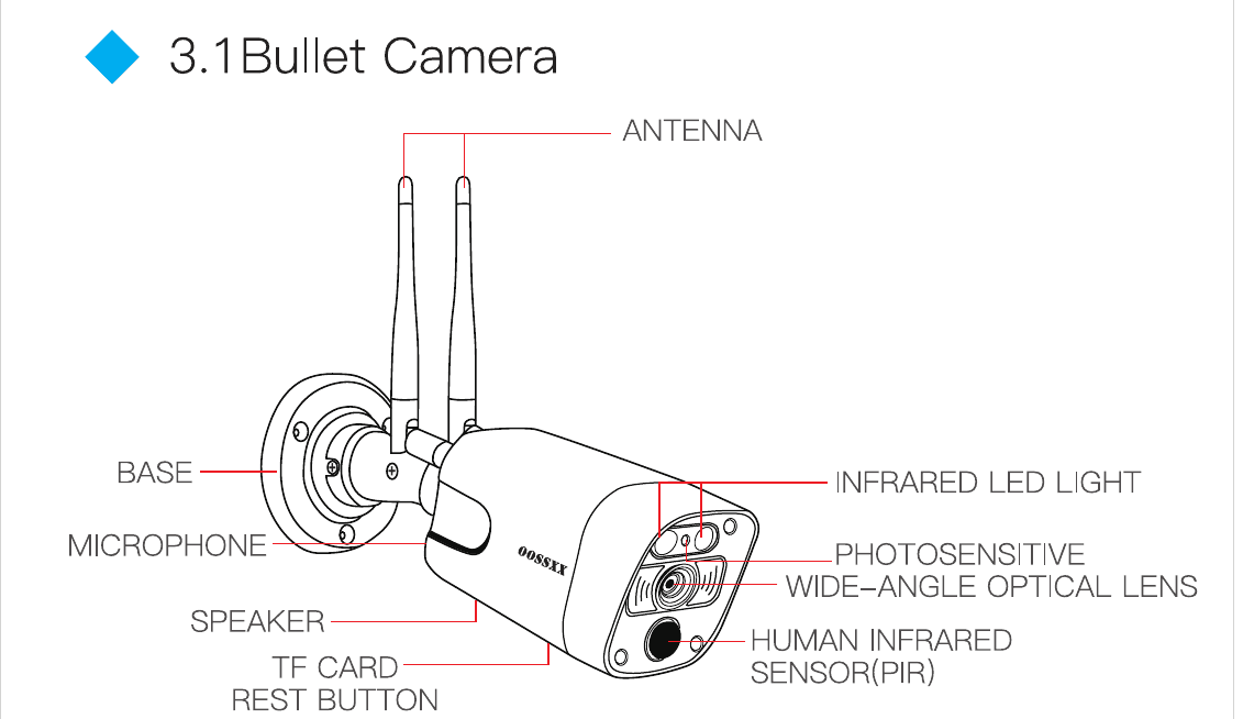
The bullet camera includes the following parts:
- Antenna
- Base
- Microphone
- Speaker
- TF Card / Reset Button
- Infrared LED Light
- Photosensitive
- Wide-Angle Optical Lens
- Human Infrared Sensor (PIR)
3.2 Station
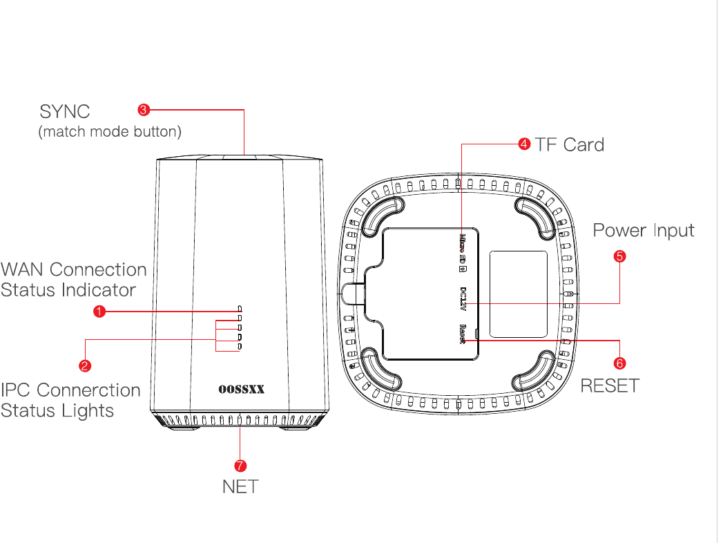
| No. | Part | Description |
|---|---|---|
| 1 | WAN Connection Status Indicator | — |
| 2 | IPC Connection Status Lights | — |
| 3 | SYNC (match mode button) | — |
| 4 | TF Card (Micro SD) | — |
| 5 | Power Input (DC12V) | — |
| 6 | RESET | — |
| 7 | NET | — |
Description
- WAN connection status indicator: When WAN/LAN is connected and works normal, it is solid on. When WAN/LAN is disconnected, it flashes slowly.
- IPC connection status lights: When cameras are connected to Station and are working normal, they are solid on, but lights flash when cameras are disconnected.
- SYNC (match code button): Press the button and hold it for 4 seconds, Station starts to pair cameras into system. Voice message gives result as MATCH CODE SUCCESS or MATCH CODE FAILS.
- TF card slot: After inserting TF card, the system defaults to motion recording.
- NET: Network cable port, connected to WIFI router.
- RESET: Long press 10 seconds to reset.
- Video: Videos are stored on TF card on Station. Once Station is connected to router, real time and playback video can be accessed remotely from cellphone/computer.
4. Working Network Diagram
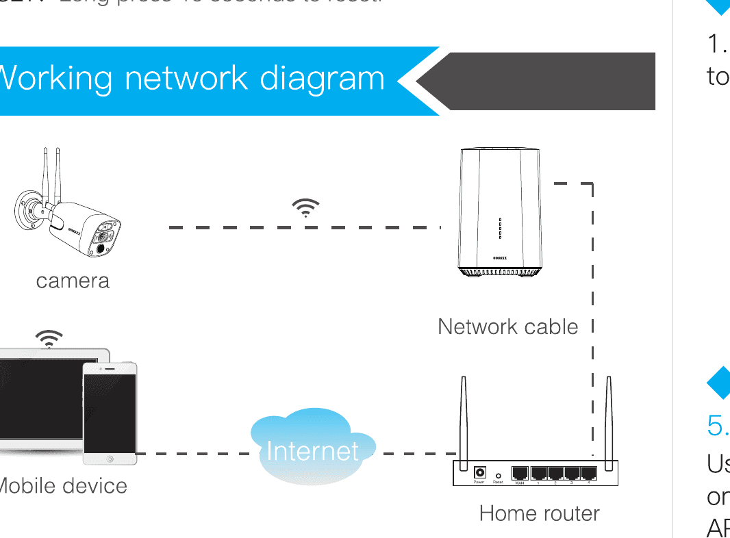
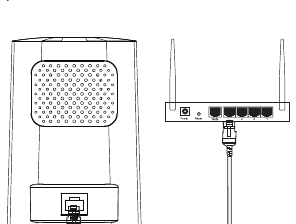
The camera connects wirelessly to the Station. The Station connects to the home router by network cable, and you access live and playback video over the Internet from a mobile device.
5. Setup and Installation
5.1 Bullet Camera
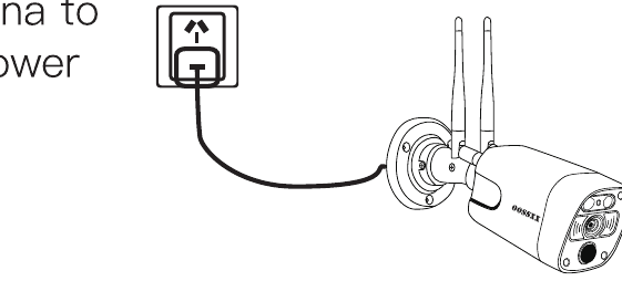
Please install the antenna to camera and connect power supply to Camera.
5.2 Station
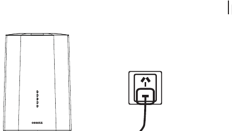
- Connect power supply to Station for power on.
- Use a network cable to connect the base station to a router that can access the Internet.
5.3 App Installation
5.3.1 APP Download and Installation
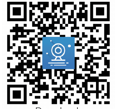
Users can search EseeCloud on APP store or IP PRO on Google Play, or scan the QR code below to install the APP.
For iOS system, it requires iOS9.0 version or above. For Android, Android 5.1 or above.
For more on the mobile app, see the ESeeCloud App User Guide.
5.3.2 Account login
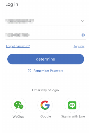
Account login: Click Register to register an account to log in the APP for the first time log in. Please use cellphone number or email address as USERNAME, and put your password which is created when register APP account.
Add the device
- When Station is powered on, connect Station to internet router by Ethernet cable.
- Open the APP and click on the + in the upper right corner to enter the scan code interface.
- Scan the QR code on gateway, and add device according to instruction in the APP. The cameras matched into the system previously will be display on the APP.
- In the add device interface, click Add.
- Set a name for the device to add successfully.
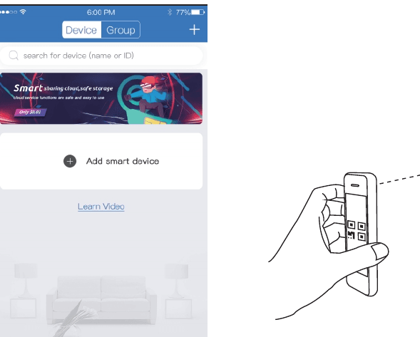
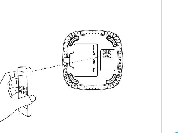
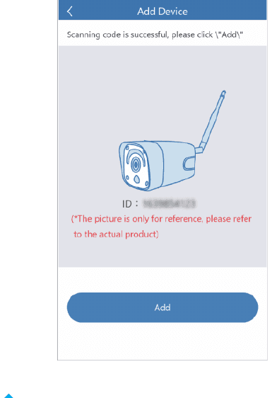
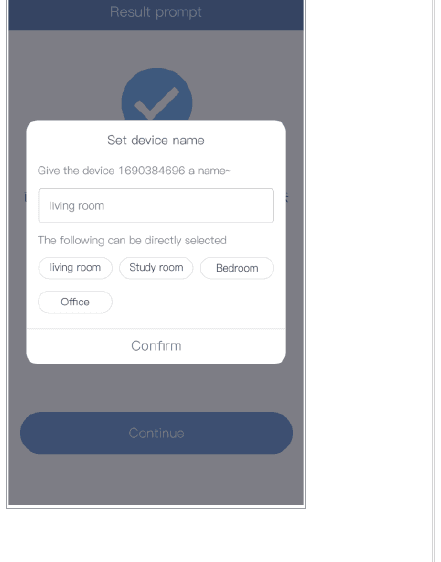
On the Add Device screen, the picture is only for reference, please refer to the actual product.
5.4 Notification, Preview and Playback
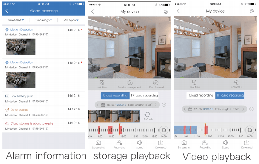
- Click the push information or info button to view the alarm information of the Station.
- Click NEWS to view motion detection alarms from the system.
- Click the playback view the video which is on the device.

5.5 Installation and placement
5.5.1 Bullet Camera
- Fix the base with screws.
- Adjust the camera's pitch angle to a proper position and tighten the fixing screws.
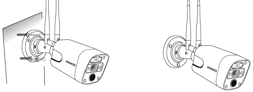
PIR is sensitive to temperature.
- Avoid to install the cameras at spots where strong air flow passing. For example, air conditioner ceiling diffuser, and ect.
- Suggest to install the camera about 7–10ft from the ground.
6. Add new Camera to Station
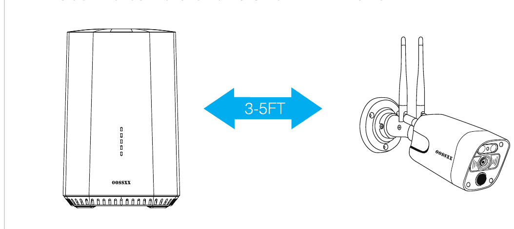
- Place the camera and station within 3–5FT.
- Press and hold SYNC button of Station for 3 seconds, system starts to match code, and signal light flashes quickly.
- Please hold rest button to rest Camera after connect power supply to camera, Camera will rest and match code station automatic.
- After 1 minute, match code ends. The corresponding channel light will be solid on, which means cameras are coded successfully.
7. FAQ
Q: What should I do if I forget my password?
A: If you have forgotten the login password of the App account, please reset the password through the Forgot Password option in the login interface as instructed.
Looking for more help? Visit the Help Center or see the ESeeCloud App User Guide.
OOSSXX HD PoE Security System Manual
Full manual for the OOSSXX HD PoE NVR security system — packing list, NVR and PoE camera specs, port diagrams, app and CMS setup, Cloud ID remote access, recording, motion detection, audio, and FAQ.
OOSSXX Solar PTZ Wireless Camera Manual
Solar Security Camera Manual for the OOSSXX solar PTZ dome camera — first charge, packing list, camera interface, network diagram, EseeCloud / IP PRO app setup, remote view and direct connection pairing, preview and playback, ceiling/wall and pole installation, charging, troubleshooting and FAQ.